Intro
I’m currently building a 3D-printed lifesize MrBaddeley R2D2, a project I inted to share more about in the future. The brains of these printed droids are historically a bunch of Arduinos with serial communications between various modules from various people. When researching which modules should power my droid, I came across the Next Gen Astromech, which aims to minimize the wiring between the modules leveraging a CAN-Bus.
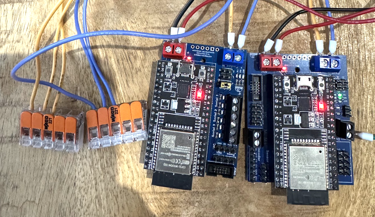
I bought a AstroCAN ProDuo board, which functions as the brain of the droid, running ShadowMD on an Arduino Mega 2560 and interfacing with the CAN-world on an ESP32 Dev Board.
The head of the droid is referred to as “dome”, and requires a motor controller. The classic droid would use a DimensionEngineering SyRen10, which is a solid basis, but lacks precise dome positioning compared to the AstroCAN AutoDome that I ordered.
Since R2s head is turning freely as often as it wants, every cable from body that is connected to the head is passed through a slipring. To reduce the required connections on the slipring, I acquired a AstroCAN Bridge to reduce the wiring to VCC, GND, CAN Low and CAN High.
I had no prior experience to working with CAN, so I went down the rabbit hole.
Since I wanted to build everything on my desk first, I assumed I could spare some efforts with the wiring, and use simple cables to get started. My “bus” was a 5-slot Wago 221. I started by just connecting the brain and the AutoDome to the bus and it wasn’t really working.
The Problem
CAN-Bus termination
In order to ensure signal integrity, CAN utilizes a 120Ohm resistor between CAN High and CAN Low at the start and the end of the bus. The AstroCAN modules solve this with a ’termination’ jumper that you can set (or not) on each module. I was initially under the impression, that CAN termination was only required on the end of the bus, which is wrong.
Learning: Measure the resistance between CAN High and CAN Low in an unpowered state. It should be as close to 60Ohms as possible.
CAN Signal Integrity
After fixing the CAN termination, I still couldn’t get the boards to see each other via CAN. Nobser was a huge help in debugging and implemented a view of what’s happening on the CAN bus via the /SETTINGS command in the --Live Peers on Bus-- segment of the output.
Sadly, mine was empty.
Using my Rigol MSO5074 digital oscilloscope I probed both CAN wires and got a weird signal that wasn’t truly differential: 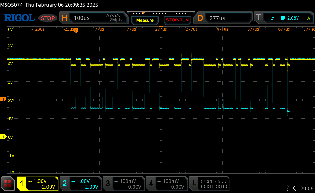
CAN Stack
While the ESP32 supports CAN natively, the AstroCAN team decided to go with a MICROCHIP MCP2515 as CAN controller and a NXP TXA1051 CAN transceiver. The ESP32 connects to the MCP2515 via serial. In the initialization output of the ESP32 boards we can see a successful initialization of the MCP2515:
> /factory
[...]
[21:42:52]Entering Configuration Mode Successful!
[21:42:52]Setting Baudrate Successful!
[21:42:52]CAN1: MCP2515 Initialized Successfully!
[21:42:52]Entering Configuration Mode Successful!
[21:42:52]Setting Baudrate Successful!
[21:42:52]CAN2: MCP2515 Initialized Successfully!
[...]
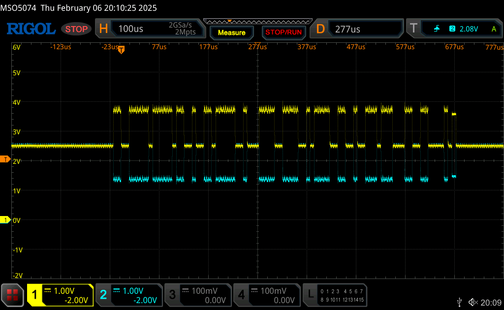
This is at least a good hint that the MCP2515 is doing what it’s supposed to do. I couldn’t figure out how to debug the NXP, so I sent my board to Nobser, who quickly replaced the NXP TJA1051 which fixed the problem. As usual, a 1EUR chip cost me hours in debugging. After replacing the CAN transceiver, the signal looked much better and I could see my peer on the CAN bus.
Lessons learned
- Always measure the resistance of your CAN bus in an unpowered state, and ensure its 60Ohms.
- Make sure your CAN signal is differential,
CAN LowandCAN Highshould be mirror opposites of each other. - Ensure you fully understand the components involved and how they communicate with each other.
- It’s always the cheapest part.
- Bonus lesson: Ensure the CAN signal travels on a twisted pair, it’s too much high frequency black magic for me to explain why, but just do it.